Copyright Statement: This article belongs to the original author. Please indicate the source when reprinting.
Original bin’s technology hut
WeChat ID: gh_6192ca0a769d
++++++++++++++++++++++++++++++++++++++++++++++++++++++++++++++++++++++++++++
Starting today, let’s talk about Netty. We all know that Netty is a high-performance asynchronous event-driven network framework.
It has an extremely elegant and concise design, high scalability, strong stability, and has very detailed and complete user documentation.
At the same time , many very useful modules are built in, which can basically be used out of the box. Users only need to write a few lines of code to quickly build a high-concurrency network application with features such as High throughput,,, and so on .Low latencyLess resource consumptionHigh performance (minimal unnecessary memory copies)
In this article, we will explore the cornerstone of Netty High throughput, which supports its features .Low latencyNetwork IO Model
Starting with Netty Network IO Model, let’s officially kick off this series of Netty source code analysis:
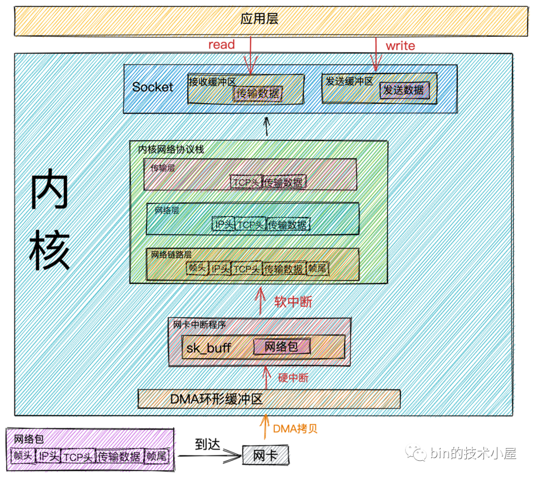
Network packet receiving process
Network packet sending and receiving process.png
- When
Network data framethe data arrives at the network card through the network transmission, the network card willDMA methodput the network data frameRingBufferinto it.
RingBufferAllocation and InitializationIt is when the network card is startedRingBuffer.RingBuffer is fullWhen it is started, the new data packet will bedroped. We can useifconfigthe command to view the situation of the network card sending and receiving data packets. Theoverrunsdata item indicates thatRingBuffer is fullat that time , it wasDropped packets. If packet loss is found, you canethtool commandincrease the RingBuffer length by.
- At that time
DMA operation completed, the network card will initiate an interrupt to the CPUHard interruptto informCPUthat network data has arrived. The CPU calls the network card driver to registerHard interrupt response routine. The network card hard interrupt response program will create a kernel data structure for the network data framesk_bufferand put the network data framecopyintosk_bufferthe CPU. Then it will initiate an interruptSoft interrupt requestto notifyKernelthat a new network data frame has arrived.
sk_buffThe buffer is a structure that maintains the network frameDoubly Linked List. Each element in the linked list is a bufferNetwork Frame. Although the TCP/IP protocol stack is divided into several layers, the transmission between the upper and lower layers actually only requires the operation of the pointer in this data structureNo data replication required.
- The kernel thread
ksoftirqddiscovers that a soft interrupt request has arrived, and then calls the one registered by the network card driverpoll Function,poll Functionand sendssk_bufferitNetwork packetsto the one registered in the kernel protocol stackip_rcv Function.
every CPUwill bindone ksoftirqdkernel threadsspecializedto processSoft interrupt response. When there are 2 CPUs, there will be two kernel threadsksoftirqd/0and .ksoftirqd/1
There is one thing to note here:
DMA copy completedafter the network card receives the data, it sends it to the CPU. If the CPU responds to it , then the data sent in the network cardHard interruptwill also be responded to in the CPU. So if you find that Linux soft interrupts consume CPU , you need to adjust the hard interrupt to put the hard interrupt up .Which CPUHard interruptHard interrupt response programSoft interrupt requestKsoftirqd thread bound to this CPUConcentrate on one coreCPU affinityBreak upUnconnected CPU cores
- In
ip_rcv functionthe figure aboveNetwork Layer,take outthe data packetIP Headerdetermines the direction of the next hop of the data packet. If the data packet is sent to the local machine, the protocol type (TCPorUDP) of the transport layer is taken out, andRemovethe data packetIP Headeris handed over to theTransport Layerprocessing in the figure above.
The processing function of the transport layer:
TCPcorresponds to the one registered in the kernel protocol stacktcp_rcv function,UDP protocolcorresponds to the one registered in the kernel protocol stackudp_rcv function.
-
When we use
TCP, when the data packet reaches the transport layer, it will be processed in the kernel protocol stack , and the TCP headertcp_rcv functionin the tcp_rcv function will be searched . If the corresponding socket is found, the transmission data in the network data packet will be copied to the . If not found, a packet will be sent .Remove the socket corresponding to thequadruple (source IP, source port, destination IP, destination port)socket receive bufferdestination unreachableicmp -
We have finished introducing the work done by the kernel when receiving network data packets. Now let’s turn our attention to the application layer. When our program
readreadssocket receive bufferdata through a system call, if the receive buffer is in the receive bufferno data, the application will make a system callblockuntil the Socket receive bufferwith data, and thenCPUputKernel Spacethe data (Socket receive buffer)copyinUser Space, and finally call the systemread returns, and then the applicationreaddata.
Performance overhead
From the perspective of the entire process of the kernel processing network data packet reception, the kernel has done a lot of work for us, and finally our application can read the network data.
Along with this comes a lot of performance overhead. Combining the network packet receiving process introduced earlier, let’s take a look at the performance overhead in the process of network packet receiving:
-
The application incurs
system callthe overhead ofUser Spacethe call to syscallKernel Spaceand the system incursreturnthe overhead of theKernel Spacecall to syscallUser Space. -
The network data transmission overhead
Kernel Spacefrom .CPU copyUser Space -
The kernel thread
ksoftirqdresponsesoft interruptoverhead. -
CPUResponsehard interruptoverhead. -
DMA copyThe overhead of network packets tommorythe
Network packet sending process

Network packet sending process.png
-
When we call a system call in an application
sendto send data, since it is a system call, the thread will undergo a transition from user mode to kernel mode. In the kernel,fdthe real Socket is first found. This Socket object records the function addresses of various protocol stacks, and thenstruct msghdrthe object is constructed to encapsulate all the data that the user needs to send in thisstruct msghdrstructure. -
The kernel protocol stack function is called
inet_sendmsg, and the sending process enters the kernel protocol stack for processing. After entering the kernel protocol stack, the kernel will find the sending function of the specific protocol on the Socket.
For example: we are using
TCP, the correspondingTCPsending function istcp_sendmsg, if soUDP, the corresponding sending function isudp_sendmsg.
- In
TCPthe sending functiontcp_sendmsg, create a kernel data structuresk_bufferand putstruct msghdrthe sending data in the structurecopyintosk_buffer. Calltcp_write_queue_tailthe function to getSocketthe tail element in the sending queue and add the newly created onesk_buffertoSocketthe tail of the sending queue.
SocketThe send queue issk_buffercomposed of oneDoubly Linked List.
At this point in the sending process, the data that the user wants to send has finally
User Spacebeen copiedKernelto . Although the data has been sent tocopythe kernel , it does not mean that the kernel will start sending it, because the data packet that the user wants to send will be sent out immediately, and it needs to meet the sending conditions. If , then this system call will return directly.Socketsend queueTCP protocolflow controlcongestion controldoes not necessarily mean thatTCP protocoldoes not meet the conditions for sendingsend`
-
If the sending conditions are met, the kernel function is called
tcp_write_xmit. In this function,Socketthe waiting to be sent in the sending queue is obtained cyclicallysk_buffer, and then the sending iscongestion ControlperformedSliding Window Management. -
Reset the data obtained from
Socketthe sending queue .sk_buffermake a copysk_buffer copyTCP HEADER
sk_bufferIn fact, it contains all the network protocolsheader. When settingTCP HEADER, just point the pointersk_bufferto the appropriate position.IP HEADERWhen setting it again later, just move the pointer, avoiding frequent memory application and copying, which is very efficient.
 sk_buffer.png
Why don’t we use the data
Socketin the send queue directlysk_bufferbut need to copy it? BecauseTCPit is supportedpacket loss retransmission. Before receiving the data from the other endACK, itsk_buffercannot be deleted. Every time the kernel calls the network card to send data, it actually passes the datask_buffer.Copy a replicaWhen the network card sends the data,sk_bufferthe copy will be released. When receiving the data from the other endACK,Socketthe data in the send queuesk_bufferwill be truly deleted.
-
After the settings
TCP Headerare completed , the kernel protocol stackTransport Layeris done. Now, by callingip_queue_xmitthe kernel function, we will officially come to the kernel protocol stackNetwork Layerprocessing.routeYou can view the local routing configuration through commands.If you use
iptablessome rules configured, thenis hitthe rules will be detected here. If you set it verycomplex netfilter rules, your thread will be in thisCPU costfunctiongreatly increased. -
Move
sk_bufferthe pointer in toIP Headerposition and setIP Header. -
Execute
netfiltersfiltering. After filtering, if the data is largerMTUthan , perform sharding. -
Check
Socketif there is a cached routing table in , if not, then find the routing item and cache it inSocket. Then set the routing table insk_buffer. - After the kernel protocol stack
Network Layeris processed, the sending process now entersNeighborhood Subsystem, which is located between andNeighborhood Subsystemin the kernel protocol stack , used to send get , and then move the pointer in to position and fill .Neighbor subsystemNetwork layerNetwork interface layerARP requestMAC addresssk_bufferMAC headerMAC header -
After
Neighborhood Subsysteprocessing,sk_buffera complete package has been encapsulatedData Frame, and then the kernel will besk_bufferhanded overNetwork Equipment Subsystemto the processor.Network Equipment SubsystemIt mainly does the following things: -
Select a send queue (
RingBuffer). Because the network card has multiple send queues, you need to select a send queue before sending. -
Will
sk_bufferbe added to the send queue. - The loop takes data out of the send queue (
RingBuffer)sk_bufferand calls the kernel functionsch_direct_xmitto send data, which will be calledNetwork Card Driverto send data.
The above processes are all executed in the kernel state of the user thread, and the CPU time occupied is the system state time (
sy). When the CPU time allocated to the user threadCPU quotais used up,NET_TX_SOFTIRQa soft interrupt of type will be triggered. The kernel threadksoftirqdwill respond to this soft interrupt and executeNET_TX_SOFTIRQthe callback function registered by the soft interrupt of typenet_tx_action. In the callback function, the driver function will be executeddev_hard_start_xmitto send data.
Note: When a
NET_TX_SOFTIRQsoft interrupt is triggered to send data, the CPU consumed afterwards will be displayed heresi, and the system state time (sy) of the user process will not be consumed.
From here we can see that the sending process and receiving process of network packets are different. When introducing the receiving process of network packets, we mentioned that the receiving data is executed
NET_RX_SOFTIRQin the kernel thread by triggering a soft interrupt of the type . In the sending process of network data packets, it is executed , and only when the thread is exhausted, the soft interrupt is triggered to send data.ksoftirqdkernel network protocol stackkernel state of user threadkernel network protocol stackCPU quotaNET_TX_SOFTIRQ
In the whole process of sending and receiving network packets,
NET_TX_SOFTIRQthe soft interrupt of type 1000 is triggered only when the network packet is sent and when the user threadCPU quotais exhausted. The soft interrupt types triggered in the remaining receiving process and the soft interrupt types triggered after sending data are all 10000.NET_RX_SOFTIRQSo this is why you check on the server/proc/softirqs, which is generally much largerNET_RXthanNET_TX10000.
-
Now the sending process has finally reached the stage where the network card actually sends data. As we mentioned earlier, whether it is the kernel state of the user thread or the trigger
NET_TX_SOFTIRQtype of soft interrupt, when sending data, it will eventually call the driver function of the network card to send data. Indev_hard_start_xmitthe network card driver function, it will be mapped to the accessible data of the network card , and finally the network card driver will send it out through the physical network card.dev_hard_start_xmitsk_buffermemory DMA areaDMAdata frame -
After the data is sent, there is one last important task, which is cleanup. After the data is sent, the network card device will
CPUsend a hard interrupt to the NIC,CPUcall the soft interrupt registered by the network card driverHard Interrupt Response Routine, trigger the type in the hard interrupt response , clean up and release inNET_RX_SOFTIRQthe callback function of the soft interrupt , clean up the sending queue ( ), and release the DMA mapping.igb_pollsk_bufferNetwork CardRingBuffer
Whether
Hard interruptit is because ofthere is data to receive, or, in other wordssend completion notification, a soft interrupt triggered from a hard interruptNET_RX_SOFTIRQ.
Here, only the copy of is released and cleared .
sk_bufferThe real onesk_bufferis still stored inSocketthe sending queue. AsTransport Layerwe mentioned in the previous processing, it has not been deleted because the transport layer needs itGuaranteed reliability.sk_bufferIt will not be deleted until it receives the ACK from the other party.
Performance overhead
Earlier we mentioned the performance overhead involved in the process of receiving network packets. Now that we have introduced the process of sending network packets, let’s take a look at the performance overhead in the process of sending data packets:
-
Just like receiving data, the application
Sytem Call sendwill incur the overhead ofUser Modeconverting from when calling and converting from when returningKernel Modeafter sending the data .System callKernel modeUser mode -
CPU quotaWhen the user thread kernel state is exhaustedNET_TX_SOFTIRQ, a soft interrupt is triggered, and the kernel responds to the overhead of the soft interrupt. -
After the network card sends data, it
CPUsends a hard interrupt to the CPU,CPUand the overhead of responding to the hard interrupt. In addition, it sends a soft interrupt in the hard interruptNET_RX_SOFTIRQto perform specific memory cleanup actions. The kernel also spends the overhead of responding to the soft interrupt. -
Memory copy overhead. Let’s review what memory copies occur during the packet transmission process:
-
In the transport layer of the kernel protocol stack,
TCPthe corresponding sending functiontcp_sendmsgwill apply to sendsk_bufferthe data to be sent by the user .copysk_buffer -
When the sending process goes from the transport layer to the network layer,
copya packet willsk_buffer copycome out and besk_buffer copypassed down. The originalsk_bufferpacket will be kept inSocketthe sending queue, waiting for the network peer .ACKThe peer will thenACKdelete theSocketpacket from the sending queuesk_buffer. If the peer does not send the packetACK, it willSocketbe sent again from the sending queue to achieveTCPreliable transmission. -
At the network layer, if it is found that the data to be sent is larger than
MTU, it will be fragmented, applying for additional sk_bufferssk_buffer, and dividing the original sk_buffer拷贝into multiple small sk_buffers.
Let’s talk about (blocking, non-blocking) and (synchronous, asynchronous) again
After we finish talking about the process of receiving and sending network data, let’s talk about the concepts that are particularly easy to confuse in IO: Blocking and Synchronization, Non-blocking and Asynchronous.
There are a lot of explanations about these two concepts in various blog posts and books on the Internet, but the author feels that they are not vivid enough and are just rigid explanations of the concepts. If the concepts are forced to fit, it actually feels like Blocking and Synchronizationthere Non-blocking and Asynchronousis no difference. After a long time, it is still vague and easy to confuse.
So the author here tries to use a more visual, easier to understand and remember way to clearly explain what is Blocking and Synchronizationand what is Synchronous vs. Asynchronous.
After the previous introduction to the network data packet receiving process, we can summarize the entire process into two stages:

Data receiving stage.png
-
Data preparation phase: In this phase, the network data packet arrives at the network card,
DMAand the data packet is copied to the memory through the hard interrupt, soft interrupt, and thenksoftirqdprocessed by the kernel protocol stack through the kernel thread, and finally the data is sent toKernel Socketthe receive buffer. -
Data copy phase: When the data arrives
Kernel Socketin the receiving buffer, the data exists inKernel Spaceand needs to be copiedcopytoUser Spacebefore it can be read by the application.
Blocking vs. Non-Blocking
The difference between blocking and non-blocking mainly occurs in the first stage: Data Prepared Phase.
When the application is initiated System Call read, the thread switches from user mode to kernel mode and reads Socketthe network data in the kernel’s receive buffer.
block
If Socketthere is no data in the kernel’s receive buffer at this time, the thread will continue waituntil Socketthere is data in the receive buffer. Then the data will be copied from kernel space to user space and System Call readreturned.

Blocking IO.png
From the figure we can see that the characteristics of blocking are in the first and second stages will wait.
Non-blocking
The main distinction between blocked and non-blocking modes is in the first stage: the data preparation stage.
In the first stage, when there is no data in the receive buffer of a socket, in blocked mode, the application thread will keep waiting. In non-blocking mode, the application thread will not wait and the system call will directly return an error flag EWOULDBLOCK.
When there is data in the receive buffer of a socket, the performance of blocked and non-blocking modes is the same. Both will proceed to the second stage where the data is copied from kernel space to user space, and then the system call returns.

From the above figure, we can see that the non-blocking feature is present in the first stage “does not wait”, but it will still occur in the second stage “waits”.
Synchronous vs. Asynchronous
The main difference between synchronous and asynchronous modes occurs in the second stage: the data copy stage.
As mentioned earlier, in the data copy stage, the primary task is to copy data from kernel space to user space. Only then can the application read the data.
When data arrives in the kernel’s receive buffer of a socket, the second stage begins.
synchronous
In the synchronous mode, after the data is ready, it is executed by the user thread. Thus, the application will experience blocking in the second stage, and the system call will not return until the data is copied from kernel space to user space. This causes a blocked state.
Both Linux’s epoll and Mac’s kqueue fall into this category of synchronous I/O.
 Synchronous IO.png
asynchronous
In the asynchronous mode, the data is copied in the second phase by the kernel. When the second phase is completed, the user thread is notified that the I/O operation has been finished, and the data is called back to the user thread. Therefore, both the data preparation phase and the data copy phase in asynchronous mode are completed by the kernel, which will not cause any blocking to the application.
Based on these features, we can see that asynchronous mode requires kernel support and is more dependent on the underlying support of the operating system.
Among the currently popular operating systems, only Windows has truly asynchronous I/O with its mature implementation of IOCP. However, Windows is rarely used as a server.
On the other hand, Linux, which is often used as a server, has an asynchronous I/O mechanism that is not mature enough, and its performance improvements are not as significant compared to NIO.
However, in Linux kernel version 5.1, Facebook’s Jens Axboe introduced a new asynchronous I/O library called io_uring to address some performance issues of the original Linux native AIO. The performance of io_uring is much better than the previous native epoll and AIO, which is worth noting.

Asynchronous IO.png
When performing network I/O operations, the I/O model used to read and write data will largely determine the I/O performance of the network framework. Therefore, the choice of I/O model is the basis for building a high-performance network framework.
The book “UNIX Network Programming” introduces five I/O models: Blocked I/O, Non-blocking I/O, I/O Multiplexing, Signal-driven I/O, and Asynchronous I/O. Each I/O model represents an upgrade and optimization of the previous one.
Next, we will introduce what problems each of these five I/O models solves, what scenarios they are suitable for, and their respective advantages and disadvantages.
Blocking IO (BIO)

Blocking IO.png
After the introduction of this concept in the previous section Blocked, I believe you can easily understand BlockedIOthe concept and process.
Since this section is about IO, let’s take a look at BlockedIOthe reading and writing process of network data under the model.
Blocking Read
When the user thread initiates reada system call, the user thread switches from user state to kernel state and checks in the kernel Socketwhether there is any data in the receive buffer.
-
SocketIf the data is in the receiving bufferwith data, the user thread copies the data in the kernel space to the user space in kernel state, and the system IO call returns. -
SocketIf the data is in the receive bufferno data, the user thread gives up the CPU and entersBlocked State. When the data arrivesSocketin the receive buffer, the user thread awakened by the kernelBlocked StateentersReady State, and then getsCPU quotathe entry through the CPU schedulingRunning Status, copies the data in the kernel space to the user space, and then the system call returns.
Blocking Write
When a user thread initiates senda system call, the user thread switches from user state to kernel state and copies the send data from user space to Socketthe send buffer in kernel space.
-
When
Socketthe sending buffer can accommodate the sending data, the user thread will write all the sending data intoSocketthe buffer, and then execute the subsequent process introduced in the “Network Packet Sending Process” section, and then return. -
When
Socketthe send buffer space is insufficient to accommodate all the send data, the user thread gives up the CPU and entersBlocked State. WhenSocketthe send buffer can accommodate all the send data, the kernel wakes up the user thread and executes the subsequent sending process.
BlockedIOThe write operation under this model is quite rigid and will not stop until all the send data is written into the send buffer.
Blocking IO Model

Blocking IO model.png
Due to Blocked IOthe read-write characteristics, Blocked IOeach request needs to be processed by a separate thread in the model. A thread can only be bound to one connection at a time. When a request comes, the server needs to create a thread to process the request.
When the concurrency of client requests suddenly increases, the server will create a large number of threads in an instant, and creating threads requires system resource overhead, which will occupy a large amount of system resources in an instant.
If the client establishes a connection but does not send data, usually in most cases, the network connection does notalways has data to read. In this case, the server thread will be idle for a long time Blocked Stateand cannot do other things. The CPU cannot be fully utilizedwill also be idle at the same time causing a lot of thread switching overhead.
Applicable scenarios
Based on the above Blocked IO Modecharacteristics, this model is only suitable for few connectionsbusiness low concurrencyscenarios.
For example, some management systems within a company usually have about 100 requests, so Blocked IO Modeit is very suitable for use. And its performance is not inferior to NIO.
This model was a commonly used IO model before C10K.
Non-Blocking IO (NIO)
Blocked IO ModeThe biggest problem is that one thread can only handle one connection. If there is no data on this connection, then this thread can only be blocked on the system IO call and cannot do other things. This is a huge waste of system resources. At the same time, a large number of thread context switches are also a huge system overhead.
So in order to solve this problem, we need to use as few threads as possible to handle more connections. , Evolution of Network IO Modelwhich is also evolved step by step according to this requirement.
Based on this requirement, the first solution None-Blocked IOemerged. We introduced None-Blockedthe concept in the previous section. Now let’s look at the characteristics None-Blocked IOof :

Non-blocking IO.png
Non-blocking read
When the user thread initiates a non-blocking readsystem call, the user thread User Spaceswitches from Kernel Modeto checking in the kernel Socketwhether there is any data arriving in the receive buffer.
-
SocketIf there is data in the receive bufferno data, the system call returns immediately with an errorEWOULDBLOCKorEAGAINerror. At this stage, the user threadwill not Blockedwillnot give upCPUcontinuepollinguntilSocketthere is data in the receive buffer. -
When data is available in the Socket receive buffer, the user thread switches to kernel mode to copy the data from the kernel space to user space. Note that during this data copying process, the application is blocked. Once the data copy is complete, the system call returns control to the application.
Non-blocking write
Blocked WriterThe style we mentioned in the introduction is Blocked Writerparticularly tough. It is very stubborn and insists on writing all the sending data Socketinto the sending buffer at once before returning. If there is not enough space in the sending buffer, it will block and wait. It is particularly tough.
In comparison, the Non-Blocked Writer is more flexible. When the send buffer lacks enough space to hold all the data, it adopts a “write as much as possible” approach. It writes whatever data it can, returns immediately, and informs the application of the number of bytes written. This allows the user thread to continuously poll and attempt to write the remaining data to the send buffer.
Non-blocking IO model

Non-blocking IO model.png
Based on the characteristics of Non-Blocked IO, there’s no need to allocate a thread for each connection like with Blocked IO. Instead, you can use one or a few threads to continuously poll each receive buffer. If no data is found, the thread moves on to the next buffer until it finds data, at which point it handles the connection’s reading and writing or passes it to a business thread pool. This approach allows handling more connections with fewer threads, fulfilling the requirement for efficiency.
Applicable scenarios
Although the Non-Blocked IO model reduces significant resource consumption and system overhead compared to the Blocked IO model, it still has a major performance issue. The Non-Blocked IO model requires the user thread to continuously initiate system calls to poll the Socket receive buffer, leading to frequent context switching between user mode and kernel mode. This overhead becomes substantial as concurrency increases, making the simple Non-Blocked IO model unsuitable for high-concurrency scenarios, and it can only handle situations up to a C10K level.
IO multiplexing
At the beginning of the section on Non-Blocked IO, we discussed how to handle more connections with as few threads as possible, which is a key challenge in network IO models. In this section, we’ll dive into the concept of IO Multiplexing. We’ll explore what multiplexing and demultiplexing mean and how they allow a single thread to manage multiple connections efficiently, which is crucial for handling high-concurrency scenarios.
Let’s use this core requirement to explain these two concepts:
-
Multi-way : Our core requirement is to use as few threads as possible to handle as many connections as possible, which
multi-wayrefers to the many connections we need to handle. -
Multiplexing :The core requirement is to use as few threads as possible and minimize system overhead while handling as many connections as possible (multi-way). In this context, “Re-Use” means efficiently utilizing limited resources. For example, using a single thread or a fixed number of threads to manage read and write events across many connections.
In other words:
-
Blocked IO Model: Each connection requires its own independent thread to handle read and write operations.
-
IO Multiplexing Model: Multiple connections can share a single thread to manage read and write operations, thereby reusing that thread across several connections.
Well, the concept of the IO multiplexing model has been explained clearly, so the key question is how do we implement this multiplexing, that is, how to let an independent thread handle the read and write events on many connections?
This question has actually been answered in the non-blocking I/O model, where the system’s non-blocking I/O calls are used to continuously poll the receiving buffers of many connections to see if there is data coming. If there is, the data is processed; if not, the system continues to poll the next socket. In this way, one thread is used to handle read and write events on many connections.
However, the biggest problem with the non-blocking I/O model is that it is necessary to constantly system calls poll the receiving buffers of each socket to see if there is any data. This frequent system calling introduces significant context switching overhead. As concurrency increases, this can also lead to very serious performance issues.
So how can we avoid frequent system calls while achieving our core needs?
This requires the operating system kernel to support such operations. We can leave the frequent polling operations to the operating system kernel, thereby avoiding the performance overhead in user space caused by frequent system calls for polling.
As we anticipated, the operating system kernel does provide such functional implementations. Let’s take a look at the implementation of the IO multiplexing model in the operating system.
select
select is provided to us by the operating system kernel as a system call. It addresses the problem in the non-blocking I/O model of constantly switching system calls and polling the receive buffers of sockets on various connections in the process. This helps to reduce the system overhead in user space and kernel space.
The select system call performs the polling operation in the kernel, thus avoiding the performance overhead in user space caused by constantly initiating polling.

select.png
-
First, when the user thread initiates the select system call, it will be in a blocked state. At this time, the user thread switches from user space to kernel space to complete a context switch for the select operation.
-
The user thread passes the file descriptor array for the sockets that need to be monitored to the kernel through the select system call. At this point, the user thread copies the file descriptor array from user space to kernel space.
The file descriptor array here is actually a BitMap, where each bit in the BitMap corresponds to a file descriptor (fd). A value of 1 at a given index indicates that there are read and write events on the corresponding fd, while a value of 0 indicates that there are no read and write events on that fd.

fd array BitMap.png
The file descriptor fd is actually an integer value representing a file. In Linux, everything is treated as a file, including sockets. In the data structure task_struct that describes all the information of a process, there is an attribute struct files_struct *files, which ultimately points to an array. This array stores a list of all the files opened by the process. The file information is encapsulated in a structure called struct file. The type stored in this array is struct file, and the index of the array is what we commonly refer to as a file descriptor (fd).
- When the user thread is in a blocked state after calling select, the kernel starts to enter and poll the fd array to check whether there is data in the receive buffer of the corresponding socket. If there is data, the corresponding value in the BitMap for that fd is set to 1. If there is no data, the value remains 0.
Note that the kernel modifies the original
fdarray!!
-
After the kernel traverses the fd array, if it finds that some fd has I/O data that has arrived, it returns the modified fd array to the user thread. At this point, the fd array is copied from kernel space to user space.
-
When the kernel returns the modified fd array to the user thread, the user thread is released from the blocked state. The user thread then starts to traverse the fd array to find the file descriptors with values of 1 in the array. Finally, the user thread initiates a system call to read the data from the corresponding sockets.
The select system call does not inform the user thread which specific fd has I/O data that has arrived. Instead, it only marks the fd entries that are I/O active, and returns the complete fd array with these markings to the user thread. Therefore, the user thread still needs to traverse the fd array to determine which specific fds have I/O data that has arrived.
- Since the kernel has modified the fd array during the traversal process, after the user thread traverses the fd array and obtains the I/O ready sockets, it needs to reset the fd array and call select again with the reset fd array. This allows the kernel to initiate a new round of traversal and polling.
API Introduction
Once we are familiar with selectthe principles, it is easy to understand what the kernel provides us select API.
int select(int maxfdp1,fd_set *readset,fd_set *writeset,fd_set *exceptset,const struct timeval *timeout)
From this select API, we can see that the select system call is used to poll (i.e., monitor) the specified set of file descriptors that the user is interested in for three types of events within a timeout period: readable, writable, and exceptional.
-
maxfdp1 :Select passes to the kernel the file descriptor with the largest value in the set of file descriptors it monitors+1, in order to limit the kernel’s traversal range. For example,selectif the set of file descriptors it monitors is{0,1,2,3,4}, thenmaxfdp1the value of is5. -
fd_set *readset: The set of file descriptors of interest for readable events.
-
fd_set *writeset: The set of file descriptors of interest for writable events.
-
fd_set *exceptset: The set of file descriptors of interest for exceptional events.
What is referred to here as fd_set is what we mentioned earlier: a file descriptor array, which is essentially a BitMap structure.
- const struct timeval *timeout: The timeout period for the select system call. During this period, if the kernel does not find any I/O ready file descriptors, it will return directly.
As mentioned in the previous section, after the kernel traverses the fd array, if any file descriptors are I/O ready, the corresponding value in the fd BitMap will be set to 1, and the modified array will be returned to the user thread.
In the user thread, you need to traverse the fd array again, find the I/O ready fds, and then initiate the actual read and write calls.
Here’s what fdwe need to use in the process of re-traversing the array in the user thread API:
-
void FD_ZERO(fd_set *fdset):Clears the specified file descriptor set, that is,fd_setit no longer contains any file descriptors. -
void FD_SET(int fd, fd_set *fdset):Add a given file descriptor to the set.
The file descriptors must be passed and reset with FD_ZERO and FD_SET before each call to select, because the file descriptor set will be modified by the kernel.
-
int FD_ISSET(int fd, fd_set *fdset): Checks whether the file descriptor specified in the set can be read or written. The user thread will traverse the file descriptor set and call this method to check whether the corresponding file descriptor is I/O ready.
-
void FD_CLR(int fd, fd_set *fdset):Remove a given file descriptor from the set
Performance overhead
Although select has addressed some of the problems associated with the frequent system calls in the non-blocking I/O model, we still found some shortcomings in the overall process:
-
When initiating and returning from a select system call, the user thread incurs one context switch from user space to kernel space and another from kernel space back to user space. Context switch overhead.
-
When initiating and returning from a select system call, the user thread needs to copy the file descriptor set from user space to kernel space, and after processing, copy it back from kernel space to user space. This results in two copies of the file descriptor set.
-
Although the original user space polling has been optimized to kernel space polling, select does not inform the user thread which specific events have occurred on the sockets. It only marks them, and the user thread still needs to use the file descriptor set to find the specific I/O ready sockets. The time complexity remains O(n) due to the need to traverse the file descriptor set.
In most cases, network connections are not always active. If
selecta large number of client connections are monitored, only a few connections are active. However, the efficiency of using polling will decrease as the number of connections increases.
-
The kernel will modify the file descriptor set, so each time the select call is re-initiated in user space, the file descriptor set needs to be reset.
-
The BitMap structure of the file descriptor set has a fixed length of 1024, so only file descriptors ranging from 0 to 1023 can be monitored.
-
select system calls are not thread-safe.
The above shortcomings of select will result in performance overhead that increases linearly as the amount of concurrency grows.
Clearly, select does not address the C10K problem and is only suitable for scenarios with about 1000 concurrent connections.
poll
pollIt is equivalent to an improved version select, but the working principle is basically the same and selectthere is no essential difference.
int poll(struct pollfd *fds, unsigned int nfds, int timeout)
struct pollfd {
    int fd;        /* File descriptor */
    short events;  /* Events to monitor */
    short revents; /* Actual events that occurred, set by the kernel */
};
selectThe file descriptor set used in the example is BitMapa structure with a fixed length of 1024 fd_set, but pollit is replaced by an pollfdarray with a structure that does not have a fixed length, so there is no limit on the maximum number of descriptors (of course, it will still be subject to the system file descriptor limit)
pollIt just improves the limit of the number of file descriptors selectthat can be monitored 1024, but does not improve the performance. It selectis essentially the same as above.
-
The file descriptor set also needs to be managed in kernel space and user space, and the time complexity for searching is still O(n).
-
The same operation needs to be done between user space and kernel space for large file descriptor sets, regardless of whether these file descriptors are ready or not. The overhead increases linearly with the number of file descriptors.
-
In both select and poll, every time you add or delete a socket that needs to be monitored, you must transfer the entire updated socket collection to the kernel.
pollIt is also not applicable to high-concurrency scenarios. It still cannot solve C10Kthe problem.
epoll
Through the above select,pollintroduction to the core principles, we can see select,pollthat the performance bottlenecks are mainly reflected in the following three places:
-
Because the kernel does not save the set of file descriptors we want to monitor, we need to pass the full set of sockets in and out each time we call select or poll. This results in frequent and extensive copying of file descriptors between user space and kernel space.
-
Since the kernel does not notify which specific sockets are I/O ready but only marks these sockets as I/O ready, when the select system call returns, the user space still needs to perform a complete traversal of the file descriptor set to determine the specific I/O ready sockets.
-
The I/O ready sockets are also identified in kernel space through traversal.
Let’s take a look epollat how to solve these problems. Before introducing epollthe core principles, we need to introduce epollsome core basic knowledge required to understand the working process.
Socket Creation
The server thread starts by calling the accept system call in a blocked state. When a client connects and completes the TCP three-way handshake, the kernel creates a corresponding socket interface as the communication channel between the server and the client.
From the perspective of the Linux kernel, everything is a file, Socketand this is no exception. Once the kernel creates a file Socket, it will Socketbe placed in the list of files opened by the current process for management.
Next, let’s take a look at the kernel data structures related to the process management of these open file lists. After understanding these data structures, we will have a clearer understanding of the role they play in the kernel. And it will be of great help Socketto our understanding of the creation process later .epoll
Manage file list structure in process

Manage file list structure in process.png
struct tast_structIt is a data structure used in the kernel to represent a process, which contains all the information of the process. In this section, we only list the attributes related to file management.
All files opened in a process are organized and managed through an fd_array. The index of the array is what we commonly refer to as a file descriptor. The array stores the corresponding file data structures of type struct file. Each time a file is opened, the kernel creates a corresponding struct file and finds a free position in the fd_array to allocate it. The index in the array is what we use as a file descriptor in user space.
For any given process, by default:
- File descriptor 0 represents stdin (standard input).
- File descriptor 1 represents stdout (standard output).
- File descriptor 2 represents stderr (standard error).
The list of files opened in the process fd_arrayis defined in a kernel data structure struct files_struct, to struct fdtablewhich a pointer struct fd **fdpoints fd_array.
Since this section discusses the data structure of the kernel network system , we will use Socketthe file type as an example:
struct fileThe pointer in the kernel data structure used to encapsulate file meta-information private_datapoints to a specific Socketstructure.
struct fileThe attributes in file_operationsdefine the file operation functions. Different file types file_operationshave different corresponding functions. For Socketthe file type, the pointer here file_operationspoints to socket_file_ops.
When we
User SpaceinitiateSocketa read or write system call, the first thing that will be called when entering the kernel isSocketthe correspondingstruct fileone pointed to insocket_file_ops. For example , whenSocketinitiatingwritea write operation, the first thing called in the kernel is the onesocket_file_opsdefined insock_write_iter.SocketWhen initiatingreada read operation, the corresponding one in the kernel is insock_read_iter.
static const struct file_operations socket_file_ops = { .owner = THIS_MODULE, .llseek = no_llseek, .read_iter = sock_read_iter, .write_iter = sock_write_iter, .poll = sock_poll, .unlocked_ioctl = sock_ioctl, .mmap = sock_mmap, .release = sock_close, .fasync = sock_fasync, .sendpage = sock_sendpage, .splice_write = generic_splice_sendpage, .splice_read = sock_splice_read, };
Socket kernel structure

Socket kernel structure.png
When we write a network program, we first create a socket, and then proceed to bind this socket. After binding, we call listen on this socket to set it up as a listening socket.
- When we call accept, the kernel will create a new socket specifically for network communication with the client. It will also assign the listen socket’s socket operations function set (inet_stream_ops) to the new socket’s ops attribute.
const struct proto_ops inet_stream_ops = { .bind = inet_bind, .connect = inet_stream_connect, .accept = inet_accept, .poll = tcp_poll, .listen = inet_listen, .sendmsg = inet_sendmsg, .recvmsg = inet_recvmsg, ...... }
It should be noted here that there are actually two sockets used for network communication: The listening socket (or listening socket). The connected socket (or connected socket).
- Then the kernel will create and initialize a struct file for the connected socket, and assign the socket file operation function set (socket_file_ops) to the f_ops pointer in the struct file. The file pointer in the struct socket will then point to the newly allocated struct file structure.
The kernel maintains two queues:
One is the connection queue that has completed the TCP three-way handshake and is in the established state. In the kernel, it is referred to as icsk_accept_queue.
One is the semi-connected queue for connections that have not yet completed the TCP three-way handshake and are in the syn_rcvd state.
- Then, when calling socket->ops->accept, what is actually invoked is the inet_accept function. This function will look for an established connection in icsk_accept_queue, and if one is found, it will directly retrieve the created struct sock from it. The struct sock object is then assigned to the sock pointer in the struct socket.
In struct socket, struct sock is a very core kernel object. It is where we define the network packet reception and transmission process mentioned in the introduction, including the receive queue, send queue, wait queue, data ready callback function pointer, and kernel protocol stack operation function set.
-
According to the parameters in the socket system call initiated at the time of creation (with the parameter value being SOCK_STREAM), the operation method implementations defined for TCP are found. These implementations are set to inet_stream_ops and tcp_prot respectively. Specifically:
- socket->ops is set to inet_stream_ops.
- sock->sk_prot is set to tcp_prot.
Here you can look back at the “Socket Kernel Structure Diagram” at the beginning of this section to sort out the relationship between them.
socketThe relevant operation interface is defined ininet_stream_opsthe function set, which is responsible for providing the interface to the user.socketThe operation interface between the kernel protocol stack is defined on the pointer in, which points tostruct sockthe protocol operation function set.sk_prottcp_prot
struct proto tcp_prot = { .name = "TCP", .owner = THIS_MODULE, .close = tcp_close, .connect = tcp_v4_connect, .disconnect = tcp_disconnect, .accept = inet_csk_accept, .keepalive = tcp_set_keepalive, .recvmsg = tcp_recvmsg, .sendmsg = tcp_sendmsg, .backlog_rcv = tcp_v4_do_rcv, ...... }
The previously mentioned system IO call will first invoke the file operation set defined in the struct file for the socket in the kernel. It will then call the socket operation function pointed to by the struct socket’s ops pointer, and finally, it will call the kernel protocol stack operation function interface set pointed to by the sk_prot pointer in struct sock.

System IO call structure.png
-
Set the function pointer
struct sockin the objectsk_data_readytosock_def_readable, andSocketthe kernel will call back this function when the data is ready. -
In struct sock, the wait queue is where the system IO call is blocked for the process fd, along with the corresponding callback function. Remember this, as we will revisit it when we introduce epoll later!
- When these core kernel objects are created, the final step is to add the corresponding objects to the list of files opened by the process (fd_array). The file descriptor returned by the system call (accept) is then given to the user program, associated with the struct file, struct socket, and struct sock.
User process blocking and wake-up principle in blocking IO
In the previous section, we mentioned BlockedIOthat when a user process initiates a system IO call, here we take readan example, the user process will 内核态check Socketwhether there is data in the corresponding receive buffer.
-
If there is data in the receive buffer of the socket, the data is copied to user space, and the system call returns.
-
If there is no data in the receive buffer of the socket, the user process will yield the CPU and enter a blocked state. When data arrives in the receive buffer, the user process will be awakened, transition to a ready state, and wait for CPU scheduling.
In this section, we will look at how the user process is Blockedstarted Socketand how Socketit is awakened. It is important to understand this process, which is very helpful for us to understand the event notification process of epoll.
-
First, when we make a system call in the user process, such as read, the user process will transition from user space to kernel space.
-
Find it in the process
struct task_structstructurefd_array, and find the correspondingSocketfile descriptor according to the file operation function in the call , and the system call corresponds to it .fdstruct filestruct filefile_operationsreadsock_read_iter -
sock_read_iterFindstruct filethe one pointed to in the functionstruct socketand call itsocket->ops->recvmsg. Here we know that the one called isinet_stream_opsdefined in the collectioninet_recvmsg. -
inet_recvmsgIt will be foundstruct sockand called in , where the function defined in the collectionsock->skprot->recvmsgis called .tcp_prottcp_recvmsg
The entire calling process can refer to the above “System IO Call Structure Diagram”
Now that we are familiar with the kernel function call stack, let’s take a look at tcp_recvmsghow the system IO call blocks the user process in the kernel function.

System IO call blocking principle.png
int tcp_recvmsg(struct kiocb *iocb, struct sock *sk, struct msghdr *msg, size_t len, int nonblock, int flags, int *addr_len) {
    // .................omitted non-core code...............
    // Access the receive queue defined in the sock object
    skb_queue_walk(&sk->sk_receive_queue, skb) {
        // .................omitted non-core code...............
    }
    // Not enough data received, call sk_wait_data
    sk_wait_data(sk, &timeo);
}
int sk_wait_data(struct sock *sk, long *timeo) {
    // Create an element for the wait queue in the struct sock
    wait_queue_t wait;
    DEFINE_WAIT(wait);

    // Call sk_sleep to get the head pointer of the wait queue in the sock object
    wait_queue_head_t *wait_queue_head = sk_sleep(sk);

    // Call prepare_to_wait to insert the newly created wait item into the wait queue,
    // and set the process state to interruptible
    prepare_to_wait(wait_queue_head, &wait, TASK_INTERRUPTIBLE);

    // Set the flag indicating that the socket is waiting for data
    set_bit(SOCK_ASYNC_WAITDATA, &sk->sk_socket->flags);

    // Yield the CPU by calling schedule_timeout, causing a context switch
    int rc = sk_wait_event(sk, timeo, !skb_queue_empty(&sk->sk_receive_queue));

    // .................omitted non-core code...............
}
- First, the waiting type on the waiting queue will be
DEFINE_WAITcreated .struct sockwait_queue_t
#define DEFINE_WAIT(name) DEFINE_WAIT_FUNC(name, autoremove_wake_function) #define DEFINE_WAIT_FUNC(name, function) \ wait_queue_t name = { \ .private = current, \ .func = function, \ .task_list = LIST_HEAD_INIT((name).task_list), \ }
The wait type wait_queue_tis privateused to associate Blockedwith the current socketuser process fd. funcIt is used to associate with the callback function registered on the wait item. The one registered here is autoremove_wake_function.
-
Call to
sk_sleep(sk)getstruct sockthe wait queue head pointer in the objectwait_queue_head_t. -
Call
prepare_to_waitto insert the newly created wait itemwait_queue_tinto the wait queue and set the process to be interruptibleINTERRUPTIBL. -
The call
sk_wait_eventgives up the CPU and the process goes into sleep state.
We have finished introducing the user process Blocked过程. The key is to understand and remember the structure of struct sockthe waiting type on the waiting queue defined in the previous section wait_queue_t. epollWe will use it again in the following introduction.
Next we will describe how the user process is awakened when the data is ready.
In the section “Network Packet Receiving Process” at the beginning of this article, we mentioned:
-
When a network data packet arrives at the network card, the network card
DMAputs the dataRingBufferinto it. -
Then initiate a hard interrupt to the CPU, create a hard interrupt response program
sk_buffer, and copy the network data tosk_bufferit. -
Then a soft interrupt is initiated, and the kernel thread ksoftirqd handles the soft interrupt. The poll function call is sent to the kernel protocol stack for layer-by-layer protocol processing.
-
In the transport layer’s tcp_rcv function, remove the TCP header and use the four-tuple (source IP, source port, destination IP, destination port) to find the corresponding Socket.
-
Finally, it will
sk_bufferbe placedSocketin the receiving queue.
The above processes are the complete process of the kernel receiving network data. Let’s take a look at how the user process is awakened after the data packet is received.

System IO call wake-up principle.png
-
When the soft interrupt places the sk_buffer on the receive queue of the Socket, the sk_data_ready callback function pointer will be called next. As we mentioned earlier, this function pointer is initialized to point to the sock_def_readable function.
-
In
sock_def_readablethe function, we will getsocket->sock->sk_wqthe waiting queue. In the function, we will find the waiting itemwake_up_commonfrom the waiting queue and call back the callback function registered on the waiting item ( ). Creating the waiting item is what we mentioned. The callback function registered here is .sk_wq一个wait_queue_tfuncwait_queue_t->funcwait_queue_tautoremove_wake_function
Even if multiple processes are blocked on the same socket, only one process will be woken up to avoid herd panic.
- In
autoremove_wake_functionthe function, wake up the process blocked on the wait item according to the associated callwait_queue_ton the wait item .privateBlocked进程fdtry_to_wake_upSocket
Remember the function pointer
wait_queue_tinfunc, where the callback functionepollwill be registered .epoll
Now epollwe have finished introducing the basic knowledge needed for understanding. After so much nagging, let’s finally get into the topic of this section epoll.
epoll_create creates an epoll object
epoll_createIt is a system call provided by the kernel to create epollobjects for us. When we call it in the user process epoll_create, the kernel will create an object for us struct eventpolland also have corresponding struct fileassociations with it. It is also necessary to put the struct eventpollobjects associated with this object struct fileinto the list of files opened by the process fd_arrayfor management.
Once you are familiar with
Socketthe creation logic of ,epollthe creation logic of is not difficult to understand.
struct eventpollThe object association points tostruct filea set of operation functions.file_operations pointereventpoll_fops
static const struct file_operations eventpoll_fops = { .release = ep_eventpoll_release; .poll = ep_eventpoll_poll, }

The overall structure of eopll in the process.png
struct eventpoll {
    // Wait queue: Processes blocked on epoll will be placed here
    wait_queue_head_t wq;

    // Ready list: Socket connections with IO ready will be placed here
    struct list_head rdllist;

    // Red-black tree used to manage all monitored socket connections
    struct rb_root rbr;

    // ...
};
- wait_queue_head_t wq: The waiting queue in epoll stores the user processes blocked on the epoll queue. When IO is ready, these blocked processes can be found through this queue and woken up to execute IO calls for reading and writing data to the socket.
Please note
Socketthe difference here from the waiting queue!!!
- struct list_head rdllist: The ready queue in epoll stores all the IO-ready data and Socket descriptors. The awakened user process can directly access the data obtained from this queue without having to traverse the entire collection of Socket descriptors again.
This is where epoll is more efficient than select and poll. With select and poll, all socket connections are returned, and we need to traverse them again in user space to find the actually active socket connections. However, epoll only returns the sockets with active IO, so the user process can directly perform IO operations.
- struct rb_root rbr: Since the red-black tree offers the best overall performance in operations like searching, insertion, and deletion, epoll uses a red-black tree internally to manage a large number of socket connections.
`select uses an array to manage connections, while poll uses a linked list to manage connections.
epoll_ctl adds a listening Socket to the epoll object
After we call to create the object epoll_createin the kernel , we can use it to add the connections we need to manage .epollstruct eventpollepoll_ctlepollSocket
- For a Socket connection, we first need to create a data structure in the epoll kernel called struct epitem. Since epoll uses a red-black tree to manage these massive socket connections for overall performance, struct epitem serves as a node in the red-black tree.

struct epitem.png
ststruct epitem {
    // Points to the associated epoll object
    struct eventpoll *ep;

    // Registered events of interest, which are the epoll_event from user space
    struct epoll_event event;

    // Points to the ready list in the epoll object
    struct list_head rdllink;

    // Points to the corresponding red-black tree node in epoll
    struct rb_node rbn;

    // Points to the socket->file structure represented by epitem and the corresponding file descriptor (fd)
    struct epoll_filefd ffd;
};
Here we focus on remembering
struct epitemthe structurerdllinkandepoll_filefdmembers, which we will use later.
- After creating the data structure represented by struct epitem in the kernel for the Socket connection, we need to create a wait item wait_queue_t and register it on the wait queue in the Socket, associating it with epoll’s callback function ep_poll_callback.
Through the foreshadowing in the previous section titled The Blocking and Waking Mechanism of User Processes in Blocked IO, I believe everyone can guess the significance of this step! At that time, the callback function registered in the wait item wait_queue_t was autoremove_wake_function. Do you remember?
The callback function of epoll
ep_poll_callbackisepollthe core of the synchronous IO event notification mechanism, and itselect,pollis also the fundamental performance difference from the kernel polling method.

epitem creates waiting items.png
Here a new data structure appears struct eppoll_entry. What is its function? You can guess its function based on the above picture!
We know that socket->sock->sk_wqthe type of the waiting queue is wait_queue_t, and we need to register the callback function on the waiting queue struct epitemrepresented by .socketepollep_poll_callback
When data arrives at the socket in the receiving queue, the kernel will invoke sk_data_ready. As described in the section on BlockedIO and the wake-up principle, the sk_data_ready function pointer is set to sk_def_readable, which then calls back the waiting item callback function registered in the waiting queue. In this process, we need to find and insert into the ready queue in epoll:
- wait_queue_t -> func
- ep_poll_callback
- epitem This ensures that the data is properly managed and available for the user process to handle.
socketThe types in the waiting queue wait_queue_tcannot be associated . So the structure epitemappears struct eppoll_entry, and its function is to associate the waiting items Socketin the waiting queue .wait_queue_tepitem
struct eppoll_entry {
    // Points to the associated epitem
    struct epitem *base;

    // Wait item in the waiting queue of the associated listening socket
    // (private = null func = ep_poll_callback)
    wait_queue_t wait;

    // Head pointer of the waiting queue in the listening socket
    wait_queue_head_t *whead;

    // ...
};
In this way, in ep_poll_callbackthe callback function, you can find it according to Socketthe waiting items in the waiting queue .waitcontainer_of宏eppoll_entryepitem
container_ofIt is a commonly used macro in the Linux kernel, which is used to obtain the pointer of the structure itself from the pointer contained in a structure. In layman’s terms, it is to obtain the first address of the entire structure variable through the first address of a member in the structure variable.
Here we need to pay attention to the setting of wait_queue_t for the wait item this time, because it is managed by the process blocked on it and will be woken up by it. The process registered in the wait item is not epoll, so it does not need to be woken up directly by epoll. Therefore, it is set here to private = null and func = ep_poll_callback. The autoremove_wake_function is used to automatically remove the wait item from the wait queue when the process is woken up. The private field is set to null because the wait item does not need to store any additional private data related to the Socket or epoll.
- When
Socketthe waiting item is created in the waiting queue and the callback functionwait_queue_tis registered , and then associated with , all that is left to do is to insert it into the red-black tree in .epollep_poll_callbackeppoll_entryepitemepitemepollstruct rb_root rbr
Here we can see another optimization of epoll: all socket connections are centrally managed through the red-black tree in the kernel. Each addition or deletion of a socket connection is incremental, rather than passing the entire set of socket connections to the kernel for each call as in select or poll. This avoids the problem of frequent and large memory copies.
epoll_wait synchronously blocks the acquisition of IO-ready Socket
-
After the user program calls epoll_wait, the kernel will first check if there are any epitem objects in the ready queue of epoll. If there are, it will encapsulate the information into the epoll_event return value.
-
If there are no epitem objects in the ready queue (eventpoll->rdllist), a new waiting item will be created. The user process will be associated with this waiting item, and a callback function will be registered on the waiting item. The waiting item will then be added to the waiting queue in epoll. The user process will yield the CPU and enter the Blocked State.

epoll_wait synchronously obtains data.png
The blocking principle in the BlockedIO model is the same as in the BlockedIO model. However, in BlockedIO, what is registered to the waiting item is default_wake_function, which is added to the waiting queue in epoll. In contrast, in BlockedIO, what is registered to the waiting item is autoremove_wake_function, and this waiting item is added to the waiting queue in socket.

Data arrives epoll_wait process.png
- After so much knowledge preparation, here is
epollthe whole workflow:

epoll_wait processing.png
-
When the network data packet arrives at the receiving buffer after being processed by the kernel protocol stack in the soft interrupt
socket, the socket’s data ready callback pointer will be called immediatelysk_data_ready, and the callback function issock_def_readable.socketFind the waiting item in the waiting queue, where the callback function registered in the waiting item isep_poll_callback. -
In the callback function
ep_poll_callback, find the object according tostruct eppoll_entrythe method in and find the encapsulated data structure through its pointer , and add it to the ready queue in.struct wait_queue_t waitcontainer_of宏eppoll_entrybasesocketstruct epitemepollrdllist -
Then check whether there is a waiting item in the waiting queue for epoll, i.e., check if there is a process blocked and waiting on epoll_wait. If there is no waiting item, the soft interrupt processing is considered complete for the IO-ready socket.
-
If there is a waiting item, the system returns to the callback function registered in the waiting item, which is default_wake_function. This function wakes up the blocked process, and encapsulates the IO-ready socket information from epitem’s rdllist into the struct epoll_event and adds it to the return queue.
-
The user process retrieves the epoll_event for the IO-ready socket and initiates a system IO call to read the data.
Talking about horizontal triggering and edge triggering
There are a lot of explanations about these two modes on the Internet, most of which are rather vague, and it feels like they are just forced to describe the concepts, which makes it difficult to understand after reading them. So here, the author would like to combine the above epollwork process and make his own interpretation of these two modes again, striving to clearly explain the similarities and differences between these two working modes.
After a detailed interpretation of the working process described above, we understand that when data arrives on a socket monitored by epoll, the soft interrupt will execute the callback function ep_poll_callback. In this function, the data structure described in epitem will be inserted into the ready queue (rdllist) in the epoll thread. Then, the user process is awakened from the waiting queue, and epoll_wait returns the IO-ready socket information to the user process, which will then handle the data.
The key difference between level triggering and edge triggering is whether the receiving buffer will be cleared when there is still data to be read .socketepoll_waitrdllist
-
Horizontal trigger : In this mode, after the user thread calls epoll_wait and acquires an IO_READY socket, it makes a system IO call to read the data from the socket. If only part of the data is read, the thread will call epoll_wait again to check if there is still data to read in the receiving buffer of the socket. If there is still data to read, the socket will be put back in the rdllist. Thus, when the IO on the socket is not fully processed, it can still be obtained by calling epoll_wait again, allowing the user process to continue handling IO events on the socket.
-
Edge trigger: In this mode,
epoll_waitit will be directly clearedrdllist, regardless ofsocketwhether there is any readable data. So in edge trigger mode, when you do not have time to processsocketthe remaining readable data in the receive buffer, call it againepoll_wait, because itrdlisthas been cleared at this time,socketit will not returnepoll_waitfrom it , so the user process will not get it againsocket, and it will not be able to perform IO processing on it. Unlesssocketthere is new IO data arriving on it , it will be put into it again according toepollthe working process .socketrdllist
In edge-triggered mode, if you have processed part of the data on a socket, you can only wait until more network data arrives on this socket again if you want to process the remaining data.
That’s right! In Netty, the default implementation for EpollSocketChannel is edge-triggered mode, which provides better performance by notifying the application only when a new event occurs. On the other hand, the JDK’s NIO default mode is level-triggered, where the application is repeatedly notified as long as there is data to be read or written.
Summary of epoll’s optimization of select and poll
- By managing a large number of connections in the kernel using epoll and a red-black tree, there is no need to pass in the listening socket file descriptor when calling epoll_wait to acquire IO-ready sockets. This avoids the overhead of copying a large number of file descriptor sets back and forth between user space and kernel space.
select,pollThe full set of file descriptors needs to be passed each time it is called, resulting in a large number of frequent copy operations.
- epoll provides notifications only for IO-ready sockets. This approach avoids the overhead of traversing all connections in user space, as only the sockets with events are reported.
select and poll will mark only the IO-ready sockets and return the entire set of file descriptors. As a result, the user program in user space needs to traverse the full set to identify the specific IO-ready sockets.
- With epoll, the user program is notified of IO-ready sockets by registering a callback function on the waiting queue. This mechanism avoids the overhead of polling in the kernel, as the kernel can directly invoke the callback function when events occur.
In most cases, a socket is not always IO-active. When dealing with a large number of connections, the use of kernel polling in select and poll to obtain IO-active sockets is a core reason for poor performance. This is because select and poll require scanning through all file descriptors to determine which ones are active, leading to inefficiencies with a large number of connections.
Based on the above epollperformance advantages, it is the network IO model used by major mainstream network frameworks and reverse proxy middleware so far.
epollThe problem can be easily solved by using the multiplexed IO model C10K.
C100kThe solution is still based on the solution of , which can be achieved naturally in most cases C10Kby epollcoordinating with thread pools and improving the performance and capacity of CPU, memory and network interfaces.C100K
Absolutely! The C10K problem, which addresses handling 10,000 concurrent connections, often relies on epoll as a core component of the solution. However, achieving such scalability involves extensive optimization across various layers, from the application to the kernel, and includes leveraging hardware to offload tasks. This offloading helps reduce interrupt response overhead and processing overhead in the kernel’s protocol stack.
Signal driver IO

Signal driver IO.png
Everyone must be familiar with this equipment. When we go to some food courts to eat, after ordering and paying, the boss will give us a signal. Then we can take this signal to find a table or do other things. When the signal lights up, it means that the meal is ready and we can go to the window to pick up the meal.
This typical scenario is very similar to the signal-driven IO model we are about to introduce.
In the signal-driven IO model, the user process initiates an IO request through a system call, such as sigaction, and registers a corresponding signal callback for a socket. At this point, the process is not blocked and can continue its work. When data is ready in the kernel, the kernel generates a SIGIO signal. This signal triggers the registered callback, notifying the process to perform the necessary IO operations.
It should be noted here that while the signal-driven IO model allows synchronous IO to avoid blocking and frequent polling when waiting for data, the user process still needs to read the data itself when notified by the kernel signal. During this data reading phase, the process can still be blocked while copying the data.
Compared with the first three IO models, the signal-driven IO model ensures that the process is not blocked while waiting for data to be ready, allowing the main loop to continue working. Therefore, theoretically, it offers better performance.
In practice, when using the TCP protocol for communication, the signal-driven IO model is rarely adopted.
The reasons are as follows:
-
Signal IO may fail to notify due to signal queue overflow when a large number of IO operations are in progress
-
SIGIO is a Unix signal that does not carry additional information. If a signal source has multiple reasons for generating a signal, the signal receiver cannot determine what happened. However, TCP sockets can generate seven different signal events. Therefore, when an application receives SIGIO, it has no way to distinguish or handle these different events.
On the other hand, the signal-driven IO model can be used for UDP communication because UDP has only a single data request event. This means that under normal circumstances, as long as the UDP process receives the SIGIO signal, it will call the read system call to read the incoming data. If an exception occurs, an error will be returned.
Let me digress here. Do you think the Blocked IO model in real life is like queuing up for food in a cafeteria? You need to wait in line to get your food while the chef prepares it. You have to wait until your food is ready.

Blocking IO.png
The IO multiplexing model is like waiting in line at the door of a restaurant. The number calling machine is akin to select, poll, or epoll, which manage all customer readiness events in a unified manner. Each customer is like a socket connection. When a customer is ready to eat, the number calling machine will notify them.

IO multiplexing.png
Asynchronous IO (AIO)
All four types of IO models introduced above involve blocking during the second stage, the data copy phase.
As explained in the previous section on “Synchronization and Asynchrony,” you can easily understand that in the asynchronous IO model, the kernel completes IO operations during the data preparation phase, and the data copy phase does not block the application. The application process only needs to reference the data in a specified array.
The main difference between asynchronous IO and signal-driven IO is that signal-driven IO notifies the application when it is possible to start an IO operation, while asynchronous IO notifies the application when the IO operation has been completed.
Let’s use a real-life example: the asynchronous IO model is like going to a private room in a high-end restaurant. You sit in the room, order your food (analogous to initiating an asynchronous IO call), and then you don’t need to worry about anything else. You can enjoy drinks and conversation, and when the food is ready, the waiter (analogous to the kernel) will bring it to your private room (analogous to user space). The whole process is seamless and without interruption.

Asynchronous IO.png
Asynchronous IO system calls need to be supported by the operating system kernel. Currently, the IOCP implementation in Windows is very mature for asynchronous IO mechanisms.
However, the asynchronous IO implementation in Linux is not yet fully mature, and the performance improvement with NIO is not very noticeable compared to epoll.
Nevertheless, in Linux kernel version 5.1, Facebook’s Jens Axboe introduced a new asynchronous IO library called io_uring, which addresses some performance issues of the original Linux native AIO. Its performance is much better than the previous native AIO implementation with epoll, and it is worth noting.
Additionally, the signal-driven IO model is not suitable for the TCP protocol, so most systems still use the IO multiplexing model.
IO thread model
In the previous introduction, we detailed the process of receiving and sending network data packets and discussed the five IO models to understand how the kernel reads network data and notifies the user thread.
The previous content analyzed the network data sending and receiving model from the perspective of kernel space. In this section, we will examine how to send and receive network data from the perspective of user space.
Compared to the kernel, the user space IO thread model is relatively simple. These user space IO thread models mainly discuss who is responsible for accepting connections, who handles IO reads and writes, who performs calculations, and how threads work together to handle sending and receiving. It is essentially a different mode of division of labor among user IO threads.
Reactor
Reactor is a model that uses different IO threads to handle NIO:
-
The IO multiplexing model uses mechanisms like select, poll, epoll, and kqueue to register and monitor IO events.
-
The monitored data will have the ready IO events distributed or dispatched to specific processing units called Handlers for corresponding IO event handling.
Through continuous monitoring and distribution of IO events using IO multiplexing technology, it resembles a continuous generation and dispatching process. This is why we call this pattern a Reactor model.
Let’s look at the following three categories of the Reactor model:
Single Reactor Single Thread

Single Reactor Single Thread
The Reactor model relies on IO multiplexing technology to monitor IO events and generate a continuous stream of ready IO events. In Linux systems, we use epoll for IO multiplexing. Let’s take the Linux system as an example:
-
Single Reactor means there is only one epoll object that listens to all events, such as connection events and read/write events.
-
Single Thread means there is only one thread performing the epoll_wait acquisition, handling the ready IO events, and processing subsequent business logic within this thread.
The Single Reactor Single Thread model is akin to running a very small restaurant where, as the owner, you handle everything: greeting customers (accept events), explaining the menu and waiting for orders (IO requests), cooking (business processing), serving food (IO responses), and bidding farewell to customers (disconnections).
Single Reactor Multithreading
As the number of customers increases (concurrent requests), it becomes apparent that handling all the tasks in the restaurant by yourself (single-threaded) is not feasible. Therefore, you need to hire more employees (multi-threaded) to assist with the various tasks.
This leads to the Single Reactor Multi-Threaded model:

Single Reactor Multithreading
-
In this mode, there is only one epoll object that listens to all IO events, and one thread is responsible for calling epoll_wait to obtain ready IO events for Sockets.
-
However, once these ready IO events are obtained, the corresponding business logic (Handler) is executed using a thread pool. This approach improves execution efficiency compared to the Single Reactor Single Thread model and leverages the advantages of multi-core CPUs.
Master-slave Reactor multithreading
When managing tasks with varying priorities, it’s crucial to distinguish what should be done more efficiently and prioritize tasks accordingly, rather than attempting to handle everything simultaneously without a clear prioritization.
As our small restaurant starts to attract more customers (increasing concurrency), we need to scale up. During this expansion, we realize that welcoming guests is the most critical task for the restaurant. We must ensure that guests are welcomed promptly and not turned away due to long wait times, even if it means that food preparation might be slower.
Thus, the Master-Slave Reactor Multi-Threaded model was developed:

Master-Slave Reactor Multithreading
-
We changed from a Single Reactor to a Multiple Reactor model. The Master Reactor is dedicated to handling the highest priority task, which is welcoming guests (handling connection events). The corresponding Handler is represented as acceptor in the figure.
-
When a connection is established and a socket is created, the acceptor objects are registered to be monitored by the Master Reactor. It listens for read events on the socket.
-
The business logic processing for reading and writing is then handed off to a thread pool.
Note: In the Slave Reactor, only read events are registered because these are triggered by the epoll kernel. Write events are triggered by the user business thread (i.e., when to send data is decided by the business logic thread). Therefore, write events should be registered by the user business thread.
The user thread registers write events only when all the data to be sent is written. It will register and wait while continuing to write the remaining data. If the user thread can write all the data in one go, no registration is necessary. If it cannot write all at once, write events are registered to handle when the buffer becomes writable again.
The Master-Slave Reactor Multithreading model is currently used in most mainstream network frameworks, such as Netty.
Proactor
Proactor
The Proactor model is based on AIO (Asynchronous I/O) and involves a different thread management approach. Unlike traditional models, where the application manages I/O events and dispatches results, the Proactor model offloads these responsibilities to the operating system kernel.
In the Proactor model:
- I/O Event Monitoring: The kernel handles monitoring I/O events.
- I/O Operation Execution: The kernel manages the execution of I/O operations.
- I/O Result Dispatch: The kernel is responsible for dispatching the results of I/O operations. In this model, the application does not need to be involved in the details of I/O operations. Instead, it just requests asynchronous I/O operations and then processes the results when the kernel notifies it. This allows the application to be completely non-blocking during the data preparation and data copy phases.
The Proactor model is beneficial because it eliminates the need for the application to actively poll or manage I/O events, leading to potentially more efficient use of resources and simplified application logic.

proactor.png
Proactor Component Introduction:
-
Completion Handler: This is a callback function defined by the user program. It is invoked by the kernel when the asynchronous I/O operation is completed, providing the result of the I/O operation.
-
Completion Event Queue: After the asynchronous I/O operation is finished, an I/O Completion Event is generated and placed in this queue.
-
Asynchronous Operation Processor: This component is responsible for executing asynchronous I/O operations. Once the operation is complete, it places the I/O Completion Event into the Completion Event Queue.
-
Proactor: Acts as an event loop dispatcher. It retrieves I/O Completion Events from the Completion Event Queue and invokes the associated completion handler for each event.
-
Initiator: This component initializes an asynchronous operation (e.g., aio_read) and registers it with the kernel, passing both the completion handler and the operation details.
Proactor Execution Process:
-
The user thread initiates an asynchronous read operation using aio_read, specifying the buffer address in user space for the kernel to use. The kernel performs the I/O operation and places the result in the specified buffer, allowing the user thread to read it directly without blocking.
-
The Initiator sets up the asynchronous read operation (aio_read) and registers it with the kernel, including the completion handler.
In the Proactor model, the focus is on I/O Completion Events: the kernel has completed the read operation and placed the result in the specified buffer, which the user thread can access directly. In contrast, in the Reactor model, the focus is on I/O Ready Events: data has arrived, but the user thread must perform the read operation itself.
-
The user thread can continue doing other tasks without waiting for the I/O operation to complete. Meanwhile, the kernel performs the I/O operation asynchronously. Once the operation is finished, the kernel generates a completion event and places it in the Completion Event Queue.
-
The Proactor then processes the completion event from the Completion Event Queue, invoking the corresponding completion handler to handle the result of the asynchronous I/O operation.
-
completion handlerComplete business logic processing in .
Reactor vs Proactor
-
Reactor is an IO thread model based on NIO (Non-blocking I/O) implementation, while Proactor is based on AIO (Asynchronous I/O) implementation.
-
Reactor focuses on I/O Ready Events, whereas Proactor focuses on I/O Completion Events.
-
In Proactor, the user program needs to pass the user-space read buffer address to the kernel. In Reactor, this is not necessary. This requirement in Proactor means that each concurrent operation needs an independent cache area, which incurs some memory overhead.
Netty’s IO model
After introducing the process of network data packet sending and receiving in the kernel, five I/O models, and two types of I/O thread models, let’s take a look at what the I/O model looks like in Netty.
As mentioned earlier, Netty supports three types of Reactor models: Single Reactor Single Thread, Single Reactor Multithreading, and Master-Slave Reactor Multithreading.
Among these, Netty typically uses the Master-Slave Reactor Multithreading model.
The three Reactor models we introduced are just design concepts. In practice, various network frameworks do not strictly adhere to these models and may have minor differences, but the general design concepts remain similar.
Let’s take a look at how the Master-Slave Reactor Multithreading model is implemented in Netty.

reactor.png in netty
-
The Reactor model appears in Netty in the form of two groups: MainReactorGroup and SubReactorGroup. These are often represented by EventLoopGroup objects. The MainReactorGroup handles connection events, while the SubReactorGroup deals with read and write events.
-
MainReactorGroup usually contains only one Reactor, responsible for the most crucial task: listening for connection events. When a connection event occurs, a corresponding acceptor (representing a NioSocketChannel) is created and initialized. Then, one of the SubReactorGroup Reactor instances is selected for registration and monitoring of Read events.
The reason for having only one Reactor in MainReactorGroup is that typically a server program binds to only one port. If multiple ports need to be bound, multiple Reactors would be configured.
-
SubReactorGroup contains multiple Reactor instances, with the number specified by system parameters like -D io.netty.eventLoopThreads. By default, the number of Reactor instances is CPU cores * 2. Each Reactor in SubReactorGroup is responsible for monitoring read and write events, with each Reactor managing a group of socket connections, thus distributing the load across multiple Reactor instances.
-
Each Reactor is assigned one IO thread, which handles obtaining I/O ready events, executing I/O operations, and processing the pipeline associated with each Socket connection.
Once a Socket connection is created, it is fixedly assigned to a Reactor, meaning that a Socket connection will only be handled by a specific IO thread. Each Socket connection is assigned a separate Pipeline instance to manage its I/O processing logic. This design ensures lock-free serialization of I/O logic processing on the same connection, preventing thread safety issues and maximizing system throughput.
Since each IO thread in a Reactor must handle not only I/O ready events and execute I/O operations, but also process the associated Pipeline, the logic within the Pipeline’s ChannelHandler should be efficient. Time-consuming business logic should be handled in a separate business thread pool to avoid impacting other connections’ I/O read and write operations, thus ensuring the overall service program’s I/O throughput.
- After the I/O request is processed in the business thread pool, the response data is propagated backward in the Pipeline using the ChannelHandlerContext reference, and eventually written back to the client.
We have completed the introduction of Netty’s I/O model. Now, let’s briefly look at how Netty supports the three Reactor models mentioned earlier.
Configuring a single Reactor and single thread
EventLoopGroup eventGroup = new NioEventLoopGroup(1);
ServerBootstrap serverBootstrap = new ServerBootstrap();
serverBootstrap.group(eventGroup);
Configuring multiple Reactor threads
// Create an EventLoopGroup with the default number of threads (usually the number of available processors)
EventLoopGroup eventGroup = new NioEventLoopGroup();

// Create a ServerBootstrap instance for server setup
ServerBootstrap serverBootstrap = new ServerBootstrap();

// Configure the ServerBootstrap to use the EventLoopGroup
serverBootstrap.group(eventGroup);
Configure master-slave Reactor multithreading
EventLoopGroup bossGroup = new NioEventLoopGroup(1);
EventLoopGroup workerGroup = new NioEventLoopGroup();
ServerBootstrap serverBootstrap = new ServerBootstrap(); serverBootstrap.group(bossGroup, workerGroup);
Summarize
This article is very informative. It uses 25 illustrations and 22,336 words to start by explaining how the kernel processes the sending and receiving of network packets, and then introduces concepts from the kernel’s perspective, which are often confusing. As a prelude, the article presents five types of I/O models and then discusses their principles and a comprehensive comparison in terms of technical evolution related to the C10K problem. Finally, the article introduces two types of I/O thread models and their implementation in frameworks like Netty.
Thank you all for listening to me talk till here, haha, now you can rub your eyes, stretch, and have a good rest.